Ignition coils are devices used to generate the high voltages needed to create a spark that ignites fuel in an internal combustion engine, and for the most part they're found in older cars, trucks and smaller low cost vehicles like lawn tractors. 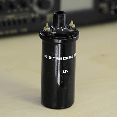 Fig. 1: Ignition Coil For the purposes of this discussion, the term ignition coil specifically refers to three terminal devices consisting of two coils of wire with a common connection which are wound on a magnetic core. 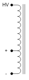 Fig. 2: Ignition Coil Schematic These devices are particularly useful for creating very high voltages and very long arcs; unfortunately, there's a lot of bad information on them out on the internet and I hope to clear some of that up here. On the other hand, there's also a lot of good information out there too, and I'll try to avoid repeating too much of it. Hopefully, this discussion will give you enough information to understand exactly how ignition coils work as well as a few ideas and projects to get you started.In automotive applications a common ignition coil circuit consisted of a voltage supply in series with a mechanical switch across the '+' and '-' terminals, with the switch being opened and closed by a cam. 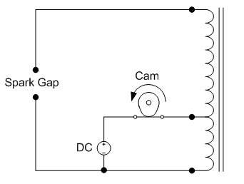 Fig. 3: Automotive Application Circuit, Switch Closed When the cam closes the switch, current flows through the "low voltage" winding, which has relatively few turns, and slowly increases the magnetic flux in the core (stores energy.) When the cam opens the switch, the current quickly decreases, causing the magnetic flux in the core to rapidly decrease as well. Since the high voltage winding (which has many more turns than the low voltage winding) is wound on the same core, it sees the same rapid decrease in magnetic flux. You may remember from earlier that the voltage across a winding is given by 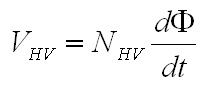 Eq. 1: Voltage Across a Winding With Changing Magnetic Flux Where VHV is the voltage across the high voltage coil, NHV is the number of turns in the high voltage coild and Φ is the magnetic flux in the core. Since the voltage of the coil is related to the rate of change in magnetic flux, and the magnetic flux is changing rapidly, a large voltage is created at the "HV" terminal. Let's look at this process in more detail. First, consider the moment at which the switch closes. It's fair to assume that at that moment the magnetic core will be completely demagnetized and the flux will be zero. Closing the switch will apply a voltage to the coil which will cause a magnetic flux to build up over time. 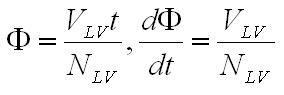 Eq.2 :Magnetic Flux Resulting from Low Voltage Winding Where Φ is the magnetic flux in the core, VLV is the voltage across the low voltage winding, and NLV is the number of turns in the low voltage winding. At some point in time the cam will open the switch again, and this is where things get a little more interesting. At this moment there is some quantity of magnetic flux stored in the magnetic core which represents some stored energy, and therefore cannot simply dissappear. Rather, there must be some mechanism for dissipating this energy and reducing the flux back to zero. In order to accomplish this, a large negative voltage appears across the low voltage winding, which by Eq. 2 indicates a decreasing magnetic flux over time. The key to the operation of the ignition coil is in the fact that the large negative voltage which appears at the low voltage winding results in a very rapid decrease in flux. Since the high voltage winding is on the same core, it will experience the same rapid decrease in magnetic flux. Substituting Eq. 2, which gives the change in flux over time, into Eq. 1, which gives the voltage of the high voltage winding as a function of flux, will give the voltage across the high voltage winding due to the voltage applied to low voltage winding. This substitution give the following result. 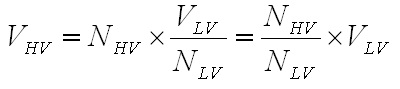 Eq. 3: Transformer Action Between Low and High Voltage Windings Notice that this equation describes transformer action, where the voltage that appears at the high voltage winding is equal to the voltage across the low voltage winding multiplied by the turns ratio of the two windings. This has the effect of multiplying the large voltage that appears at the low voltage winding in order to reset the core by the turns ratio of the two windings. With a turns ratio of 100:1 and a reset voltage at the low voltage winding of 300V, a voltage of 30 kV will appear across the high voltage winding. 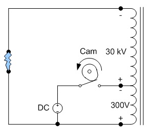 Fig. 4: Automotive Application Circuit, Switch Open I have not yet seen a good explanation elsewhere as to what factors control the low voltage winding reset voltage. I threw out 300 V just to put some numbers on the problem, but how is that voltage actually determined? The short answer is that when the low voltage winding is disconnected the voltage across it, and consequently the voltage across the high voltage winding, will increase until the energy finds somewhere to go. The particulars of the voltage that this happens at, the path the energy takes and the duration of the event are all dependent on the circuitry that's connected to the coil. Here are a few examples of some of the more common circuits. Let's start with the circuit shown in Fig. 3 and Fig. 4. There is an important omission that differentiates this circuit with those found in automobiles which drastically reduces the performance of the circuit as shown. At the moment when the switch starts to open (as in Fig. 4) an increasing voltage potential occurs across the switch, which quickly breaks down to form an arc at a relatively low voltage. The arc voltage then becomes the force causes the magnetic flux to fall, and at a rate much lower than we would like. Of course, this causes the output voltage to be much lower as well, and a weak arc (or no arc at all) occurs. 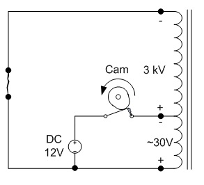 Fig. 5: Low Performance From Ignition Coild Due to Switch Arcing The actual circuit used in automotive ignition systems includes a capacitor across the switch in order to prevent arcing and increase performance. While the switch is closed there is very little voltage across it (perhaps a few milivolts) which causes the capacitor to completely discharge. At the moment when the switch begins to open the capacitor forces the voltage across it to remain at zero (or very nearly zero) volts, preventing an arc from forming. The capacitor provides another important function in this circuit by providing a path for the low voltage winding current to flow when the switch opens. 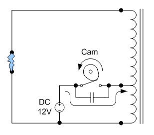 Fig. 6: Improved Performance with Capacitor Across Switch So how exactly, besides preventing the switch from arcing, does the capacitor increase the voltage at the low voltage winding? When the switch opens all of the current flowing in the low voltage winding begins to flow through the capacitor, until all of the energy stored in the inductor is transfered to the capacitor. The equation for the energy stored in each components is given below. 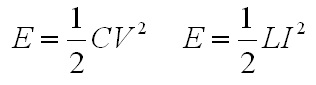 Eq. 4: Energy Stored in a A) Capacitor and B) Inductor These equations can be used to estimate the maximum voltage achieved across the low voltage winding. Assume that the low voltage winding inductance is 5 mH, the peak current in the low voltage winding is 5 A, the inductor does not saturate, and we'd like 300 V across the low voltage winding. Using equation 4B we can calculate that 5 mH carrying 5 A stores 62.5 mJ of energy. If this energy is completely transfered to the capacitor, we can use equation 4A to calculate that we need a capacitance of 1.39 uF to reach 300 V. The actual voltage will be limited if either the low voltage or high voltage windings are able to create an arc before the capacitor is fully charged. That largely covers how an ignition coil operates in a vehicle, but chances are that most non-vehicular applications would preferably not include a cam and mechanical switch. The switch's function can easily be replaced by a transistor or MOSFET, but some care is required in designing the circuit so as not to damage any of the relatively delicate semiconductor devices. I've seen a few places on the internet where the author declares semiconductor switches unreliable for ignition coil applications, but this is not so. There is no reason why a semiconductor switch can't be used reliably in this application, and it's more likely that their circuit was poorly designed. First, observe what happens when the mechanical switch is simply replaced with a MOSFET. The switch is moved to the low side of the coil, but this doesn't change the operation of the circuit, it just makes it easier to drive the MOSFET's gate. 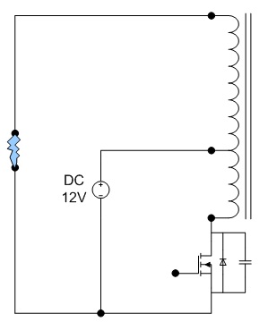 Fig. 7: Ignition Coil With Mosfet Switch That's simple enough - the switch is replaced by a MOSFET (with the body diode and parasitic capacitor shown,) but how is it different than using a mechanical switch? There are two main differences. First, the capacitance across the MOSFET is tiny compared to capacitors typically used with mechanical switches. A 400 V 10 A MOSFET might have a capacitance on the order of 100 pF, or about 10,000 times smaller than the capacitor in the earlier automotive example. The practical implication of this is that the voltage across the MOSFET will increase much more quickly, and to a much higher voltage than in the automotive application. Using the example of 5 mH and 5 A, the voltage across the MOSFET would theoretically rise to 1.25 GV (1,250 Million Volts!) Now, obviously those sort of outrageous voltages would never be reached. Something else in the circuit would give way well before the voltage reached that high (I'm looking at you, MOSFET.) The other difference, which seems pretty obvious is that there is no longer a mechanically opening contact. In a mechanical system with uncontrolled voltage build-up an arc would form across the switch and dissipate all of that energy. There is no such safety mechanism with the MOSFET. So what would happen in the MOSFET circuit? Well, there are two possibilities. The best case would be that an arc would jump between two points in the circuit that are close together before the voltage was able to build up to a level where anything in the circuit was damaged. More likely, and more damaging, would be that the voltage across the MOSFET would build up to the breakdown voltage and the MOSFET would begin to conduct in an event called "avalanche." A large enough avalanche will cause significant damage to a MOSFET, or destroy it completely in one shot. Despite the potential damage caused, many MOSFETs can withstand some level of avalanche safely, and if the circuit is designed correctly, may be able to withstand repetitive avalanches. The key parameters to designing a circuit that can withstand avalanche are usually listed on a MOSFET's datasheet as "Single Pulse Avalanche Energy" and "Repetitive Avalanche Energy" (if the MOSFET is avalanche rated at all.) These parameters specify the maximum energy the MOSFET can safely absorb without damage. A datasheet might list the single pulse avalanche energy for a particular switch to be 500 mJ. In this case, equation 4B would be used to compute the the amount of energy stored in the inductance that will be switched off and compared to the datasheet value. If this hypothetical device were used to switch the 5 mH, 5 A inductor in the earlier example (which we calculated to be 62.5 mJ) we would expect the switch to survive a single avalanche. This same device might have a repetitive avalanche energy of 15 mJ, in which case there would be no garauntee that the device would survive or operate correctly after multiple avalanches. In either case, the MOSFET will be absorbing the energy of the avalanches, and may heat up substantially. Care must be taken to ensure that the avalanche energies do not exceed the datasheet specifications AND that the device will stay within the datasheet temperature specifications. Of course, allowing the MOSFET to operate in avalanche mode may not be the best option, and there are other ways to limit the voltage it experiences. The most obvious method is to add an external capacitance across the MOSFET, just like with the mechanical switch. The capacitance can be sized, as before, to ensure a certain voltage or prevent the circuit from exceeding a certain voltage. A more robust solution is to add a capacitor in series with a resistor (typically called a "snubber.") This allows the energy absorbed by the capacitor to be dissipated in the external resistor, rather than the MOSFET itself. It also prevents a large current spike from the capacitor through the MOSFET when it first switches on. There are other types of snubber circuits as well, some of which various combinations of resistors, capacitors, and diodes. Those are the basics of ignition coils that I wanted to discuss. Here are some additional pages with more detailed information on several ignition coil related subjects.
[ Back to Main ] Questions?
Comments? Suggestions? E-Mail me at MyElectricEngine@gmail.com
Copyright 2007-2010 by Matthew Krolak - All Rights Reserved. Don't copy my stuff without asking first. |