The nozzle for my MPD thruster was probably one of the most straight-forward components to design for this project. The basic requirements for this component were that it could support tremendous currents flowing between the two electrodes, that it allowed for high propellant flow rates, and that its geometry allowed for the generation of high levels of thrust. First, let's look at the requirements for generating high levels of thrust. The equation that describes the thrust output of this device is [1] 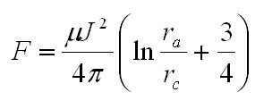 Eq. 1: Thrust Developed From a MPD Thruster where F is the thrust in Newtons, J is the total current, ra is the radius to the inside of the anode, and rc is the radius of the cathode, and the general configuration of the nozzle is as shown below. 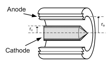 Fig. 1: Nozzle Schematic, Cut-Away View The exact form of equation 1 isn't critical at this point, but let's note that the total thrust developed by the nozzle is governed by a) the ratio of anode to cathode radius and b) the total current flowing through the nozzle. One possible approach to this problem is to choose a cathode radius large enough to withstand the large currents flowing through it, and then set the anode radius as large as is reasonably feasible. I chose a 0.25" diameter Tungsten cathode due to Tungsten's ability to withstand very high temperatures and my inability to find anything larger at a reasonable price. The ratio ra / rc was set to about 3.5, so the anode radius worked out to .45". This ratio was chosen primarily to keep the distance between the cathode and anode small enough to allow the ignition circuit to work.The construction of the nozzle involves three major parts: a Lexan mounting plate, a Tungsten cathode with mounting terminals, and a large copper anode assembly. These three parts are shown individually below with mounting hardware. 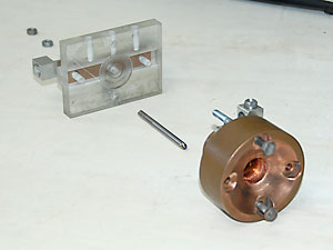 Fig. 2: Nozzle Parts, "exploded" view. The anode is composed of two sections of copper soldered together with a gas injection port and terminal blocks. 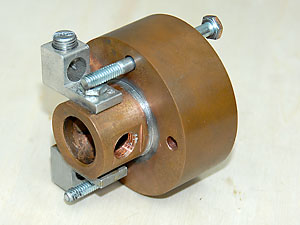 Fig. 3: Rear of Anode Assembly The two aluminum terminal blocks are used to make the electrical connection to the anode. The threaded hole on the right of the nozzle is the gas injection port. The entire assembly sits flush against the Lexan mount, which is also the insulator that separates the anode and cathode. 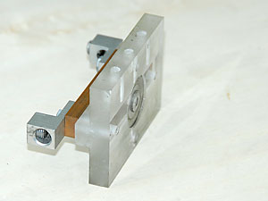 Fig. 4: (a) Lexan Mount and (b) Mount with Cathode Attached. Figure 4a shows the Lexan mount. The cathode is press-fit into the copper bar on the rear of the mount through the hole in the center of the mount. The anode then sits snuggly in the grove around the cathode, and is bolted in to place. 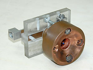 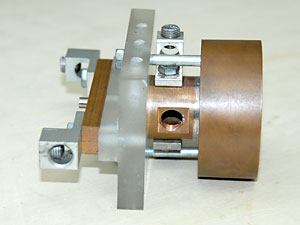 Fig. 5: (a) Front View of Nozzle Assembly (b) Side View of Nozzle Assembly. Figure 5a shows the anode mounted to the Lexan mount, and figure 5b shows all of the electrical and mechanical connections, including the anode mounting bolts, the gas injection port, and both pairs of electrical connections to the electrodes, as well as a portion of the Tungsten cathode protruding from the copper bar into which is it press-fit. The entire nozzle assembly is shown below. 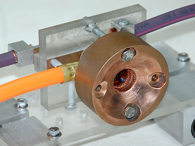 Fig. 6: Nozzle Assembly Mounted to Track Cart w/Electrical and Gas Connections References [1] R. G. Jahn, Physics of Electric Propulsion, [ Back to MPD Thruster ] [ Back to Main ] Questions?
Comments? Suggestions? E-Mail me at MyElectricEngine@gmail.com
Copyright 2007-2010 by Matthew Krolak - All Rights Reserved. Don't copy my stuff without asking first. |