The purpose of the ignition circuit is to accurately and reliably switch on large currents across an air gap, such as may be found in an electric engine nozzle or an electric welder. Completing a circuit across an air gap can be accomplished by jumping a spark between the two electrodes, which creates a low resistance path for current through the ionized channel that we see as a spark. This is most easily accomplished by applying a voltage across the gap that exceeds the gap's breakdown potential. From this brief discussion we can extract two basic requirements of the ignition circuit - that it be able to impose a large voltage across a spark gap and that the gap is then able to carrier large currents, perhaps tens of thousands of amps. This, unfortunately, is not as easy as it sounds - but lets think this through and see what we can come up with. (To skip the theoretical stuff and get right to the construction details, click here.) To start with, we have some power source and a spark gap connected together as shown below. 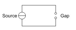 Fig. 1: Source Supply Connected to Air Gap Just to get started, let's say that the gap is 1cm long. This would require approximately 30kV be applied across the gap in order to get the air in the gap to breakdown and spark. This will require some other voltage source (we don't expect to need nearly 30kV from the main source), as shown in figure 2. 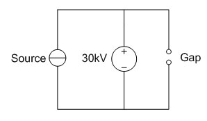 Fig. 2: Source and High Voltage Connected in Parallel Here we encounter our first problem, namely that in applying the voltage required to create a spark between the two electrodes of the gap we've also applied a very large voltage directly across our source. Even though we haven't said anything about the design or construction of our source, it's a pretty safe bet that this is going to cause damage to the supply, if not completely destroy it. Using ideal components this would be a trivial problem; we could just place a diode between the main source and the high voltage source. 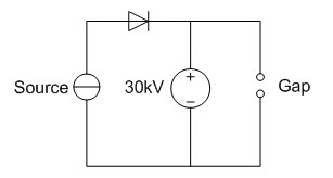 Fig. 3: Source and High Voltage Decoupled by Diode While that seems like a reasonable solution, finding a diode that can both withstand 30kV reverse bias and survive while carrying several hundreds or thousands of amps is for all practical purposes impossible. Another solution would be to use a high voltage AC source instead of a DC source and then replace the diode with an inductor to block the high AC voltage.  Fig. 4: Source and High Voltage Decoupled by Inductor This certainly solves the reverse breakdown requirement problem with the diode in the previous design, but again, an actual inductor with a large enough inductance to block the high AC voltage and a large enough core to keep from saturating at several thousand amps would be completely impractical. The big problem with all of these designs so far is that they attempt to put the high voltage in parallel with the source, and decoupling the source from the high voltage is very difficult. A more practical configuration places the main source and the high voltage source in series. If we stick with the AC high voltage source, we can even make it easily controllable by using a transformer. Fig. 5: Source and High Voltage Connected in Series This arrangement allows a high voltage to be applied to the gap without simultaneously imposing that voltage across the source as well. If we make transformer T an air core transformer, then there is no saturation issue or weight issue associated with a large iron core. So, if we put a switch between the high voltage AC source and the transformer, we can control when a spark is created across the gap and consequently when the source is able to drive current through the now ionized air gap. Huzzah! The high voltage AC source is somewhat more complicated than simply using a high voltage transformer. Here I used a circuit which is very similar to one found in Tesla Coils. Its purpose is to generate a very high frequency high AC voltage which can be used to drive the air core transformer. 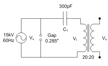 Fig. 6: High Frequency Starter Circuit Let's briefly explore this circuit's operation. The neon sign transformer's output voltage will oscillate at 60Hz, from 0V to approximately 21kV. The spark gap, which measures 0.285" across, will breakdown and create a short circuit at just about 21kV (the very top of the sine wave.) Prior to the gap sparking, the capacitor will have charged to approximately 21kV. At the moment when the gap sparks the neon transformer is removed from the circuit and the capacitor and inductor formed by the transformer resonate at a high frequency. This high frequency high voltage signal will be transfered to the output of the circuit by the air core transformer. The resulting waveforms are shown below in figure 7. 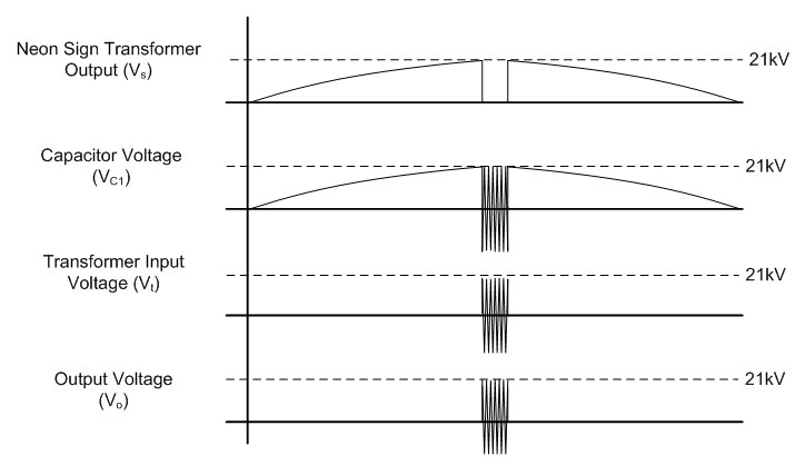 Fig. 7: High Frequency Starter Waveforms This is the method that I used to construct my ignition circuit, and is very similar to the Miller HF-15 welding arc starter. I originally found the schematics for this device here. OK, now let's look at the details and construction of this circuit.
So, the most practical topology for the ignition circuit places an air core transformer between the source and the air gap, which is in turn connected to a high voltage AC source as shown in figure 5. Air Core Transformer The air core transformer is simply two wires wrapped around a PVC tube. I used 20 turns for both windings; the high current winding is made of 00 AWG copper cable and the high voltage winding is made of 18 AWG 30kV wire. 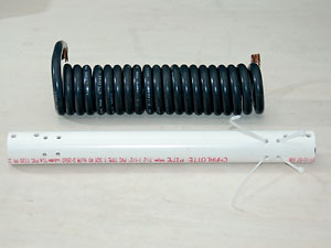 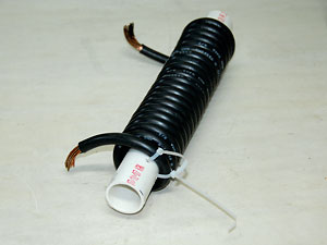 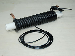 Fig. 8: Air Core Transformer Construction Since the 00 AWG cable that I used is very stiff I drilled two holes approximately 1 cable diameter apart and zip-tied the cable down on one end while winding it. The high voltage winding was wound so that it sat on top of and between each turn of the high current winding. This is important because it maximizes the coupling between the two coils, which is already weak due to the lack of an iron core. 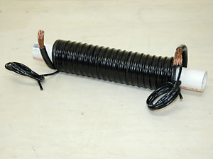 Fig. 9: High Voltage Windings and Completed Transformer
Before I go on to explain how I built this circuit I would like to make it understood that the voltages in this circuit as well as it's output are high enough to kill you instantly. No second chances, no trips to the hospital, just dead. It should go without saying that if you're not 100% sure how to work with circuits like these you shouldn't go anywhere near them. High Voltage AC Source I used a neon transformer, two 590pF 30kV capacitors, a custom made spark gap, and high voltage wire to construct this circuit. The first thing I obtained was a neon sign transformer from eBay (I get a lot of my parts from there.) It's a big, heavy, ugly Magnetek 15kV 30mA neon transformer, as shown below. It cost about $90 not including shipping charges, which were significant on account of it's weight. The small 30kV 590pF knob capacitors also came from eBay, as well as the high voltage wire. 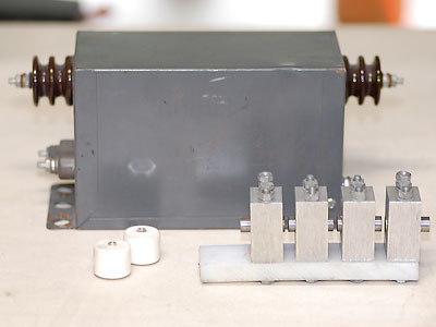 Fig. 10: Ignition Circuit Parts The spark gap was somewhat more difficult to obtain. In the end I wound up making it myself out of 4 pieces of aluminum bar stock, 4 tool steel electrodes, a non-conductive Delrin block, and assorted hardware. The electrode spacings are adjustable via a set screw on the top of each block, and the total gap was set to about 0.285". The large aluminum blocks also serve as heatsinks, since prolonged operation can generate a significant amount of heat. It isn't obvious in the photo, but the Delrin has started to warp slightly from the heat. 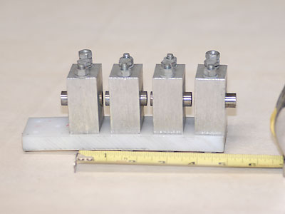 Fig. 11: Custom Spark Gap The entire assembly was mounted to a sheet of 3/8" Lexan as shown below. 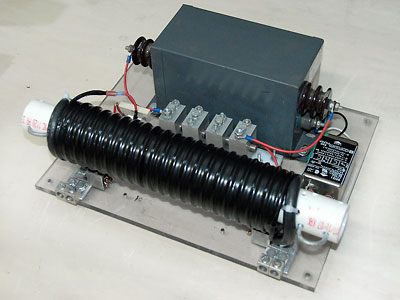 Fig. 12: Complete Ignition Circuit Assembly In the rear you can see the neon sign transformer, which connects directly to the spark gap. The spark gap is then connected in series via the high voltage winding on the transformer, the doorknob capacitors, and a 1 Ohm 10 Watt resistor. The extra resistor doesn't really effect the operation of the LC tank circuit much, but it does limit the current that flows in the high voltage winding during the discharge through the high current winding. [ Back to MPD Thruster ] [ Back to Main ] visitors since September 2007 Questions? Comments? Suggestions? E-Mail me at MyElectricEngine@gmail.com Copyright 2007-2010 by Matthew Krolak - All Rights Reserved. Don't copy my stuff without asking first. |