My first ignition circuit was designed for use in the lab because of its ease of construction, however the design paid little attention to the size, weight, or interference caused by the device. This design will address these issues by replacing the large neon transformer and spark gap with a solid state switching converter and a L-C resonant tank circuit. First, a 30 second introduction to resonance. Let's start by looking at the impedance of inductors and capacitors at varying frequencies. 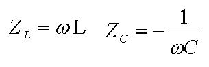 Eq. 1: Impedance of Inductors and Capacitors at Varying Frequencies So, for example, a 1 Henry inductor attached to an AC source with a frequency of 1 rad/sec has an impedance of 1 Ohm. If the AC source has an RMS value of 1 V, this would naturally lead to a RMS current flowing through the inductor of 1 A. Similarly, a 1 Farad capacitor attached to an AC source with a frequency of 1 rad/sec would have an impedance of -1 Ohm. For the purposes of calculating RMS currents, we can ignore the negative sign of the impedance, so again if we assume the source to have an RMS voltage of 1 volt, then 1 A RMS would flow through the capacitor. Now, let's combine these two elements in series. 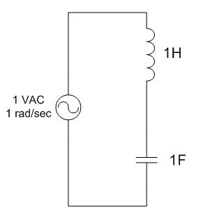 Fig. 1: Inductor and Capacitor Connected in Series Now, we know the impedance of the inductor is 1 Ohm, and the impedance of the capacitor is -1 Ohm, and impedances in series add, so that means that this circuit has an impedance of 0 Ohms? Yup - if you were to be able to construct this circuit out of ideal components then the current through the LC "tank" would be infinite. This will occur at the frequency where the impedances of the inductor and capacitor cancel out, a frequecy know as the "resonant frequency" of the LC tank. So, even though the terminal voltage applied to the LC tank is only 1 V, the infinite current will create infinite voltages across the two components. This is a very useful property when we're looking to create a high voltage ignition circuit, since it only requires three basic elements to generate huge voltages. The acutal implementation is somewhat more complex since we have to use real components, but the basic idea is the same - apply an AC voltage to an LC tank at the resonant frequency in order to generate large voltages for the purpose of striking an arc. The resonant frequency concept is very important, so the equations that govern the various parameters are equally important to this design. The first important equation relates the inductance and capacitance of the tank to the resonant frequency. The resonant frequecy is given by the equation: 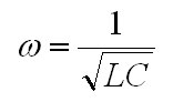 Eq.2: Resonance Frequency So, how do you build such a device for the purpose of striking an arc? Let's assume we already have an inductor and capacitor and just work on the voltage source. The example above assumes a source that produces a sinusoidal AC voltage, but we can modify this to make the implementation easier and more efficient. Using transistors we can easily apply a square wave, and that will work as well. For this, a nice and simple circuit is the full-bridge topology, shown below in figure 2. 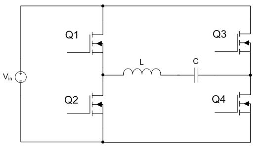 Fig. 2: Full Bridge In this circuit, if Q1 and Q4 are turned on, the inductor side is pulled high and the capacitor side is pulled to ground. Alternately, turning on Q2 and Q3 pulls the inductor end of the tank to ground and the capacitor end high. This alternately applies +Vin and -Vin across the LC tank, creating a square AC voltage across the LC tank. As mentioned earlier, this will create large currents in the tank and create very high voltages across the tank components. As with the original ark striking circuit, using a coupling transformer is a convenient way to transfer the high voltage to the spark gap of the nozzle. In this case, the coupling transformer is most easily incorporated by replacing inductor L in figure 2 with the magnetizing inductance of the coupling transformer, as shown below. 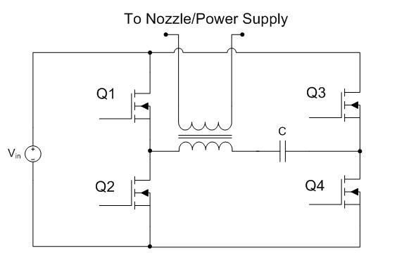 Fig. 3: Coupling Transformer Replaces Inductor So, that's the basic layout of the new ignition circuit. Now, there are some practical design issues to cover since infinite voltages and currents are clearly not possible or feasible. The first issue is that there is a limit to how fast the transistors in this circuit can be switched, which in turn limits how high the resonant frequency of the tank can be. Currently, standard switching devices can be purchased that would allow a reasonant frequency from about 500 kHz to about 1.5 MHz. More expensive RF transistors would allow this range to be extended into the hundreds of MHz, but for a much higher price. Ideally, this arraingement results in unbounded voltages and currents, but of course non-idealities such as resistances in the components prevent this. Let's look at what happens using real components. Here's a simulation of a LC tank circuit with a capacitance of 2.533nF and an inductance of 10uH with a resonant frequency of 1 MHz, excited by a +/- 1 V square wave. 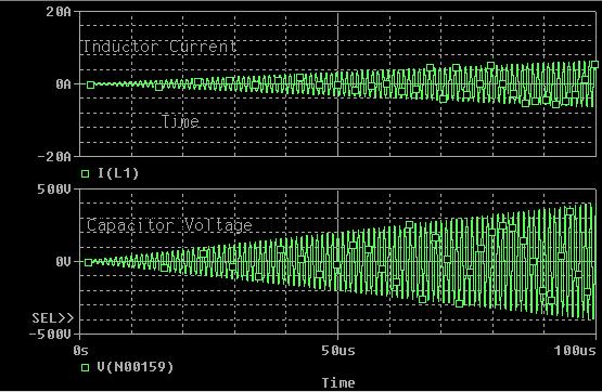 Fig. 4: Simulated LC Tank Circuit From this simulation we see that the voltages and currents don't immediately explode to infinity, rather they grow linearly. This is reasonable, since infinite voltages and currents implies infinite energy, and we know that any real source has a certain internal resistance that limits the ammount of energy that can be added. Let's try this simulation again, but change the capacitor's and inductor's value. Here's the same simulation, but with 100uH and 253.3pF. 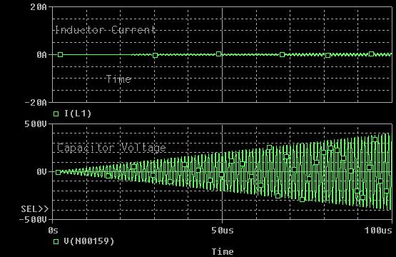 Fig. 5: Simulated LC Tank Circuit This is interesting because the same high voltage is generated in the same ammount of time as before, but this time with less current flowing in the circuit. This is important because the main stress on the bridge switches is the current, and this trade-off between inductance and capacitance let's us control how much current is needed to produce a given voltage. These values can be related by assuming that the total energy in the circuit over one switching cycle remains relatively constant. That means that when the capacitor is charged up to it's maximum voltage it is storing the same amount of energy that the inductor is when maximum current is flowing through it. The equations for a capacitor's and inductor's stored energy are given below. 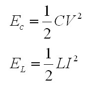 Eq. 3a and 3b: Energy stored in an inductor and capacitor Choosing a maximum capacitor voltage (based on the length of the gap that the ignitor needs to jump an arc across) and an arbitrary capacitor voltage sets the maximum energy stored in the LC tank. In this case, the maximum voltage was selected to be 80kV (high enough to arc across a 1" gap) and the capacitance was selected to be 120pF. This gives a maximum circuit energy of 0.384 J. There are now two options in how the design can proceed. Either the inductor can be chosen, setting the resonant frequency, or the the resonant frequency can be chosen and the inductance calculated from that. In this case it is important that the resonant frequency be set high, so 1 MHz was chosen. Using equation 2, the inductance is calculated to be 211 uH. The inductor will store a maximum energy of 0.384 J, which by equation 3b requires 60 A peak (43 Arms). The capacitance can be achieved by placing 5 600pF 30kV capacitors in series (based on what I have laying around.) Here the current is chosen to be as high as is reasonably possible because the ignition not only needs to be able to jump an arc, but also to put enough current through the arc to force the arc voltage to collapse below the capacitor bank supply voltage (otherwise there is a spark, but the caps won't discharge.) Since the arc voltage falls with increased current, a large current is necessary. As with the original design, the inductor was layed out as a solenoid type, however this time a ferrite core is required to reach the necessary inductance. This is a little more difficult considering the relatively large inductance, current, and flux required. Starting with the equation for inductance of a solenoid type inductor 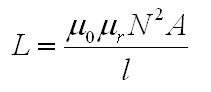 Eq. 4: Inductance for a magnetic core solenoid inductor where u0 is the permeability of free space, ur is the relative permeability of the magnetic material, N is the number of turns, A is the cross sectional area of the magnetic material in square meters, and l is the mean path length through the magnetic material, and the equation for the flux density in the core 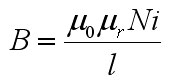 Eq. 5: Flux density in the inductor's core a suitable core can be chosen. The first limitation is the switching frequency, which is quite high, and therefore limits the materials that can be used. Ferroxcube's 3F4 material is a good choice to meet these requirements. Anticipating the need for a lot of magnetic material to support large magnetic fluxes, two I100/25/25-3F4 cores were placed end to end to give a core about 8" long and 1" square on it's face. Under worst case conditions this material has a relative permeability of 900. Using equation 4, 6 turns are required to obtain at least 211 uH. This immediately presents a problem. Since the relative permeability of this material can reach 1,800 under certain conditions, flux densities as high as 7.9 T could occur, hugely exceeding this material's maximum flux density of 0.41 T (0.35 T is a safer number.) The maximum flux can be controlled by adding an air gap to the inductor's core. Recall that in a magnetic circuit with an air gap, the reluctance of the air gap dominates the overall reluctance of the circuit. The reluctance of an air gap can be calculated as 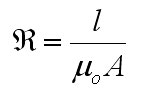 Eq. 6: Air gap reluctance with the inductance given as 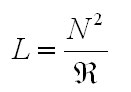 Eq. 7: Inductance as a function of turns and reluctance By varying the parameters the magnetic flux can be reduced to 0.35 T with 14 turns around a core with a 3mm gap and a crossectional area of 4" square. This new core requires 8 of the 1"x1"x4" cores initially chosen. That a lot of magnetic material, but it works. With the LC tank completed, we move on to the switching circuit. This part of the design focuses on choosing switches for the bridge that can withstand the large currents, and that can switch fast enough. [ Back to MPD Thruster ] [ Back to Main ] Questions?
Comments? Suggestions? E-Mail me at MyElectricEngine@gmail.com
Copyright 2007-2010 by Matthew Krolak - All Rights Reserved. Don't copy my stuff without asking first. |