This section is going to focus on some of the more practical characteristics of arc discharges, as opposed to the theoretical material covered in the first section. One of the most important characteristics of the arc discharge is its V-I curve. This curve describes how the arc voltage changes with respect to the arc current, and has many important implications.  Fig 1: V-I Curve of a Particular Arc [1] These curves were determined by Hertha Ayrton for arcs between carbon electrodes with the spark gap distance as a parameter and are particular to her setup. Therefore, they are not valid for different electrode materials, geometries, and spacings. They do, however, illustrate some important principles that can be applied to more general scenarios. An interesting characteristic to start with is the relatively flat portion of the V-I curve at higher currents. From a practical perspective, this can greatly simplify design and analysis since the arc voltage is relatively insensitive to changes in current. For example, in designing a switching arc power supply, a much larger output current ripple might be acceptable and therefore much smaller and less expensive magnetics could be used. I haven't been able to find much information on V-I curves that extend to hundreds or thousands of Amps, but the experience I have seems to indicate that the arc voltage remains steady (within perhaps +/- 10 V) well into the 10s and 100s of thousands of amps. At some point I'll have my own experimental data to confirm or contradict this, and I'll be sure to post it when it's available. But what should we make of this flat region? How do we explain it in the context of the physical phenomena discussed earlier? The most intuitive place to start is probably with the anode and cathode voltage drop regions, which you may remember are two invisibly thin regions at the electrode surfaces where the arc attaches, and which exhibit a consistent voltage drop (on the order of 10 - 20 V or so at both electrodes) which is a function of the electrode material. The cathode drop region is particularly important, since the positive ion bombardment at its surface creates the heat that frees electrons which in turn flow through the discharge. The simple explanation is that increasing the arc current increases the thermal power delivered to the cathode surface, and this in turn generates more free electrons and later, more free positive ions. With additional charge carriers available, an increased arc current can be supported given the same arc voltage. In this way, the arc is self-sustaining. It's worth noting that since the anode and cathode drop regions are so thin, they have very little surface area through which they can conduct heat to the surrounding air. Therefore, most of the energy consumed by the drop regions (arc current times anode or cathode drop) goes into thermal heating of the electrode. Part of this energy goes to releasing electrons from the cathode surface, most of it is either radiated or conducted away from the arc attachment region. That addresses the relatively constant voltage region associated with large currents, but what of the region where arc voltage increases quickly with decreasing arc current? For an explanation to this, we can look again to magnetic constriction of the arc. You may recall that at high arc currents a strong magnetic field is created which exerts an inward force on the flowing charges and opposed thermal expansion of the gases, confining the discharge to a small cross section. At low arc currents a relatively small magnetic field is created, which exerts very little inward force, which does little to oppose thermal expansion of the gases. This expansion results in an arc which is much cooler, and consequently is less completely ionized. This reduction in charge carriers results in lower conductivity of the positive column, and an increase in arc voltage.  Fig. 2: Low Current Arc (~30mA) Incidentally, the effect of a cooler arc on conductance and arc voltage is also relevant when energy is extracted from the arc in an application such as heating another gas. In such an application heat from the positive column would be transfered out of the arc, resulting in lower temperature and lower conductivity, with the ultimate effect of increasing the arc voltage for a given current. Another way to think about this is as an energy balance. For a given current a certain amount of power is required to maintain electron generation at the cathode, replace heat lost to radiation and conduction, etc. This requires a certain arc voltage to deliver the required power (arc current time arc voltage.) If additional power is taken out of the arc to perform some other task, then the arc voltage must increase in order to supply that additional power. OK, back to the V-I curve... The V-I curve is also an important consideration when starting an arc. Consider a circuit consisting of a number of ideal voltage supplies connected to two electrodes. As shown in Fig. 3. 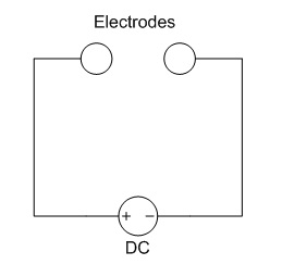 Fig. 3: Supply and Electrode Circuit Suppose the V-I curve has already been established for these electrodes, and is graphed with the V-I characteristics of the power supplies (constant voltages.) 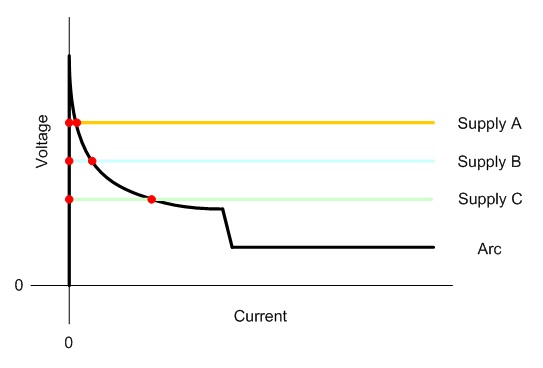 Fig. 4: Electrode and Power Supply V-I Characteristics Note that the arc V-I curve extends upwards along the Y axis at zero current until it meets the curve which resembles those shown in Fig. 1. In this case, the supply lines for the three supplies shown (the constant voltage lines representing ideal supplies) each intersect the load line (arc V-I curve) twice, once at zero current and again at some positive current. In this case, all three supplies can only reach the zero current point, as none of them are capable of generating a high enough voltage to cause a current to flow. Clearly, this indicates that the supplies shown in Fig. 4 are not capable of causing the spark gap breakdown which is necessary to start the arc. Now, let's modify the circuit from Fig. 3 to include some resistance is series with the supply. 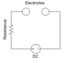 Fig. 5: Modified Circuit with Resistance If the supply voltage is higher than the gap breakdown voltage, there is now one intersection between the source and load lines, which represents a stable operating point which the supply is able to reach. 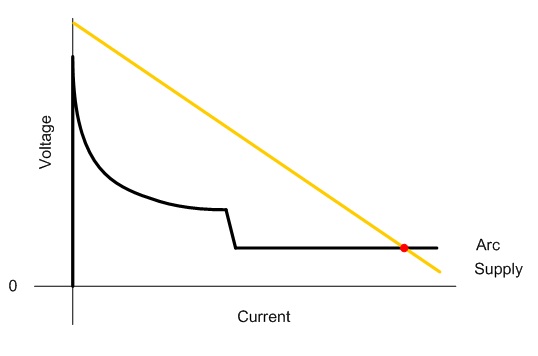 Fig. 6: Modified Source and Load Lines This is critically important when designing an ignition circuit, since some ignition circuits have very high source impedance and therefore can only supply very limited current. An ignition circuit may be able to cause a breakdown between the electrodes, but if it is unable to supply enough current to cause the arc voltage to fall below the voltage of the supply, the arc will extinguish when the ignition circuit is turned off. 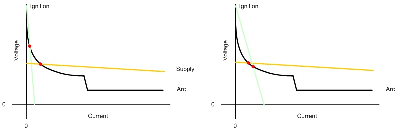 Fig. 7: A) Improperly Matched Ignition Circuit and Supply B) Properly Matched Ignition and Supply Fig. 7a illustrates a mismatched ignition and supply. Due to the ignition circuit's high source impedance, it can only supply a small amount of current to the arc, and the arc voltage never falls low enough for the supply to be able to provide current to the arc. In Fig. 7b the lower source impedance enables the ignition circuit to operate below the source line allowing the supply to provide current to the arc. Note that the supply and arc line will intersect at another point far off the right side of the chart, which will ultimately be the stable operating point of the circuit. References [1] J. D. Cobine, Gaseous Conductors, [ Back to Main ] Questions?
Comments? Suggestions? E-Mail me at MyElectricEngine@gmail.com
Copyright 2007-2010 by Matthew Krolak - All Rights Reserved. Don't copy my stuff without asking first. |